Free vibration of the circular plate
EXPERIMENTAL METHODOLOGY
EQUATION OF MOTION: CLASSICAL PLATE THEORY
1.1 Equation of Motion
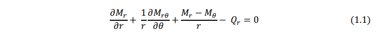
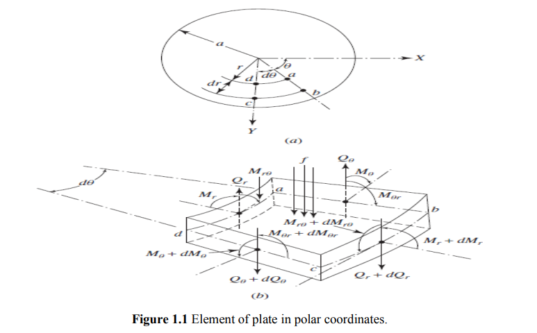
Consider an infinitesimal element of the plate in polar coordinates as shown in Fig. 1.1. In this figure the radial moment Mr, tangential moment Mθ, twisting moments Mrθ and Mθr, and the transverse shear forces Qr and Qθ, are shown on the positive and negative edges of the element. The equations of motion of the plate can be derived in polar coordinates by considering the dynamic equilibrium of the element shown in Fig. 1.1 as follows: Moment equilibrium about the tangential (θ) direction:
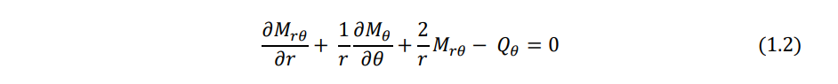
Moment equilibrium about the radial (R) direction:
Force equilibrium in the z direction:

Equations (1.1)-(1.3) can be combined to derive a single equation of motion in terms of the moment resultants Mr, Mθ, and Mrθ, By substituting the moment resultants in terms of the transverse displacement w, the final equation of motion, shown in Eq. (1.16), can be obtained.
The coordinate transformation technique can also be used to derive the equation of motion in polar coordinates from the corresponding equation in Cartesian coordinates, as indicated below.
1.2 Transformation of Relations
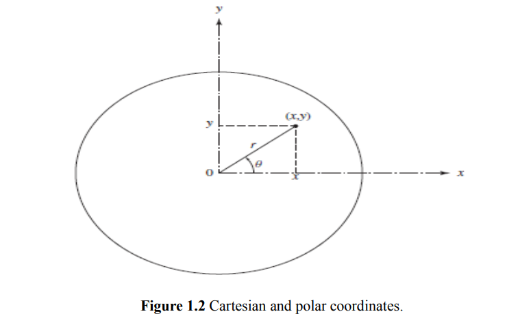
The Cartesian and polar coordinates of a point P are related as (Fig. 1.2)
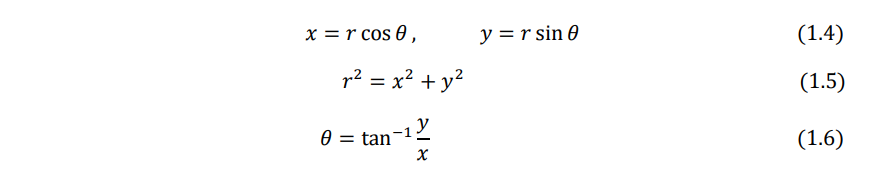
From Eqs. (1.5) and (1.6), we obtain

Similarly, Eqs. (1.6) and (1.4) give

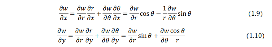
Since the deflection of the plate w is a function of r and θ, the chain rule of differentiation yields
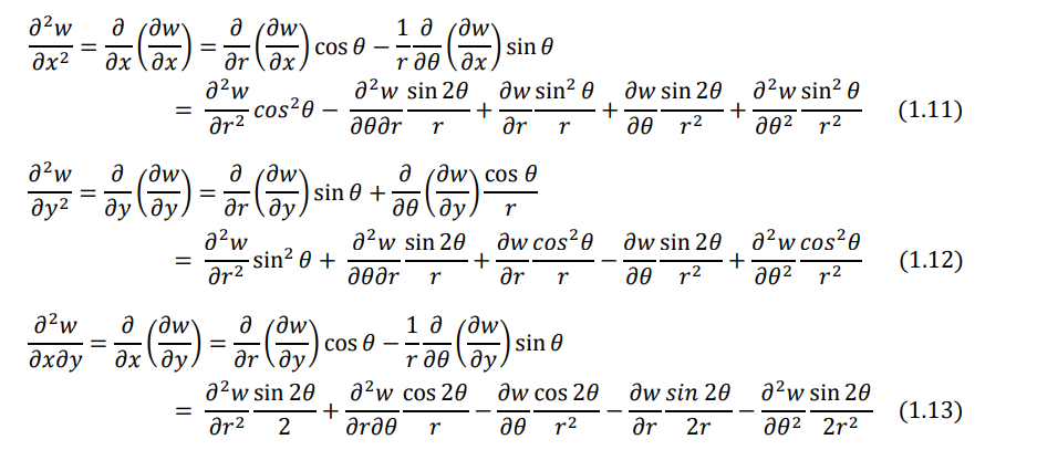
For the expressions ∂2w ∕ ∂x2, ∂2 w ∕ ∂x∂y , and ∂ 2w ∕ ∂y2, the operations ∂/∂x and ∂/∂y of Eqs. (1.9) and (1.10) are repeated to obtain
By adding Eqs. (1.11) and (1.12), we obtain

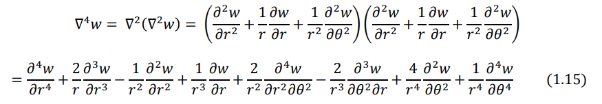
By repeating the operation ∇2 twice, we can express
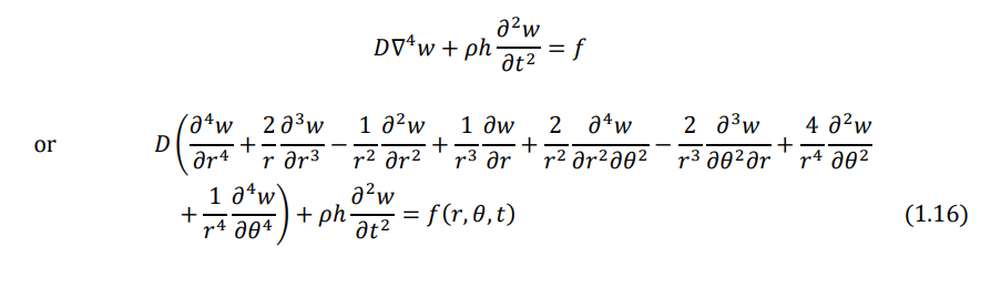
Using Eqs. (1.9), (1.10), and (1.11) in the equation of motion for the forced transverse vibration of a circular plate can be expressed as
1.3 Moment and Force Resultants
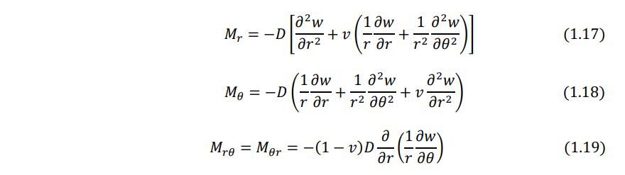
Using the transformation procedure, the moment resultant - transverse displacement relations can be obtained as:
Similarly, the shear force resultants can be expressed as
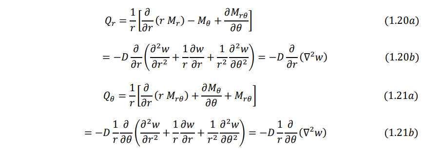
The effective transverse shear forces can be written as
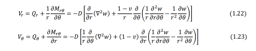
Note that the Laplacian operator appearing in Eqs. (1.20) - (1.23) is given in polar coordinates by Eq. (1.14).
1.4 Boundary Conditions
- Clamped, fixed, or built-in edge. The deflection and slope (normal to the boundary) must be zero:
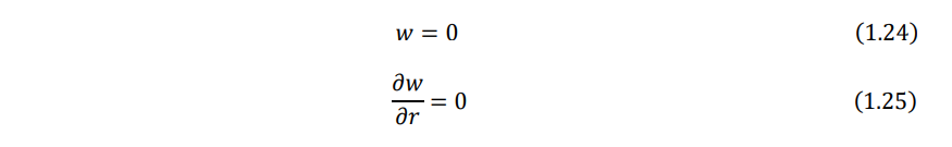
where r denotes the radial (normal) direction to the boundary.
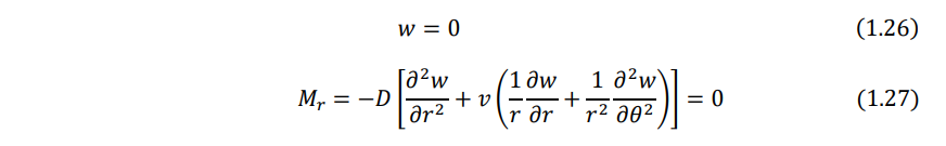
- Simply supported edge. The deflection and bending moment resultant must be zero:
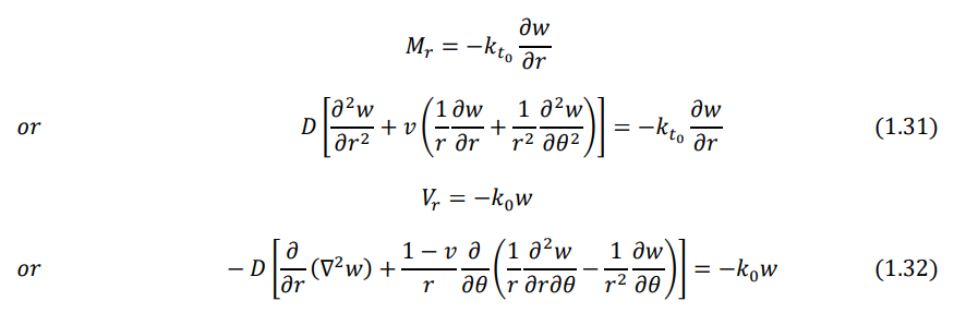
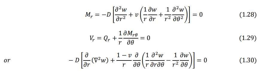
- Free edge. The bending moment resultant and the effective shear force resultant on the edge must be zero:
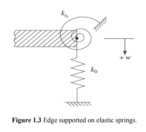
- Edge supported on elastic springs. If the edge is supported on linear and torsional springs all around as shown in Fig. 1.3, the boundary conditions can be stated as follows: